Humidity is the amount of vapor exists in a fixed gas. It is mostly used as a measure of water content of the air. In oil and gas industry, there is lots of equipment operating based on humidification and dehumidification theorem. They involve the transfer of material between a pure liquid phase and a gas which is insoluble in the liquid. Cooling towers, dryers and quenchers (saturators) are famous examples. In humidification, both heat transfer and mass transfer are important and influence one another.
In the following section, we will review some important humidification terms and theories in chemical engineering. Our basis of calculation is a unit mass of vapor-free gas, where vapor means the gaseous form of the component also present as liquid. For the purpose of this study, detailed derivations of formulas are not provided. In addition, mixture of gas and vapor is assumed to follow the ideal gas law.
Humidity
Humidity (H) is the mass of vapor carried by a unit mass of vapor-free gas. Therefore, it is only related to the partial pressure (P) of the vapor in the gas. If the vapor is referred to as component A and the gas as component B, then humidity can be illustrated as:
H=\frac{M_{A}P_{A}}{M_{B}(1-P_{A})}Where MA and MB are molecular weights of component A and B.
Relative humidity
Relative humidity (HR) is the ratio of partial pressure of the vapor to the vapor pressure of the liquid P*A at the gas temperature. Relative humidity is usually expressed on a percentage basis. Unlike humidity, relative humidity is one of the properties that is mostly reported for site’s conditions in refinery and petrochemical industry.
H_{R}=100\frac{P_{A}}{P^{*}_{A}}Dew point
Dew point is the lowest temperature of a vapor-gas mixture can be reached without condensation. At the dew point, the vapor-gas mixture is become saturated.
Adiabatic saturation temperature- Adiabatic cooling line
Adiabatic saturation temperature (TS) obtained by adiabatically evaporating the maximum amount of liquid in the gas until the gas reaches maximum (saturation) humidity. For a water-air system, adiabatic saturation temperature is the lowest temperature of air, which can be reached by evaporation of water adiabatically. Water is often sprayed into stream of gas to bring the gas to saturation. Steam desuperheater (attemperator) and air coolers are famous examples. By performing an enthalpy balance over this adiabatic saturation process, the following equation can be derived to find adiabatic saturation temperature. This equation is known as adiabatic cooling line.
\frac{H-H_{S}}{T-T_{S}}=-\frac{C_{S}}{\lambda _{S}} C_{S}=Cp_{B}+Cp_{A}\: H
Where CpA and CpB are specific heat of vapor and gas. HS is saturation humidity and \lambda _{S} is the latent heat of liquid at TS. By having temperature and humidity of the inlet air-water mixture, one can find adiabatic saturation temperature via adiabatic cooling line from humidity chart.
Assumptions for air-water system:
- The water is sprayed at temperature TS
- The remaining water is at TS
- The leaving gas is at TS
Wet bulb temperature- Psychrometric line
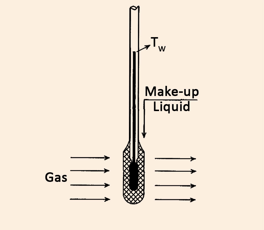
Wet bulb temperature (Tw) is a non-equilibrium steady state temperature. For an air-water system, it is obtained by a thermometer immersed in a water-soaked cloth with a stream of air passing over in adiabatic condition. Wet bulb temperature is almost independent of gas velocity.
Both mass and heat transfer rates between gas and liquid are not in equilibrium and have to be considered in order to determine wet bulb temperature. In fact, at steady state wet bulb temperature, heat and mass are being transferred between liquid and gas dynamically. The wet bulb temperature differs fundamentally from the adiabatic saturation temperature. However, for air-water mixtures they are almost identical making it easy to find the wet bulb temperature from humidity chart.

Theory of wet bulb temperature
The following equation can be used to determine wet bulb temperature. This equation is known as psychrometric line. It can be plotted on humidity chart as a straight line and intersecting the 100 percent line (100% relative humidity) to obtain wet bulb temperature. Tw is a function of actual gas temperature, known as dry bulb temperature (T), and humidity.
\frac{H-H_{w}}{T-T_{w}}=-\frac{h_{y}}{M_{B}k_{y}\lambda_{w}}Where ky is mass transfer coefficient and hy is heat transfer coefficient between gas and liquid surface. For air-water system \frac{h_{y}}{M_{B}k_{y}}\cong C_{S} (Lewis relation). Therefore, psychrometric lines and adiabatic cooling lines become the same.
Assumptions:
- The surrounding cloth must be completely wet
- The velocity of the gas should be large enough to decrease the influence of radiation heat transfer.
- Make-up liquid should be supplied to the bulb at the wet bulb temperature.
- The mass of the liquid is so small in comparison with the gas phase that there is only a negligible change in the properties of the gas.
- The temperature of the liquid is constant and there is no temperature gradient through the cloth.
- The sensible heat is small in comparison with latent heat and is neglected.
Wet bulb temperature is always lower than actual gas temperature except in places where relative humidity is equal to 100%. In such a case: Twet bulb= Tdry bulb= Tdew point
Humidity (Psychrometric) chart
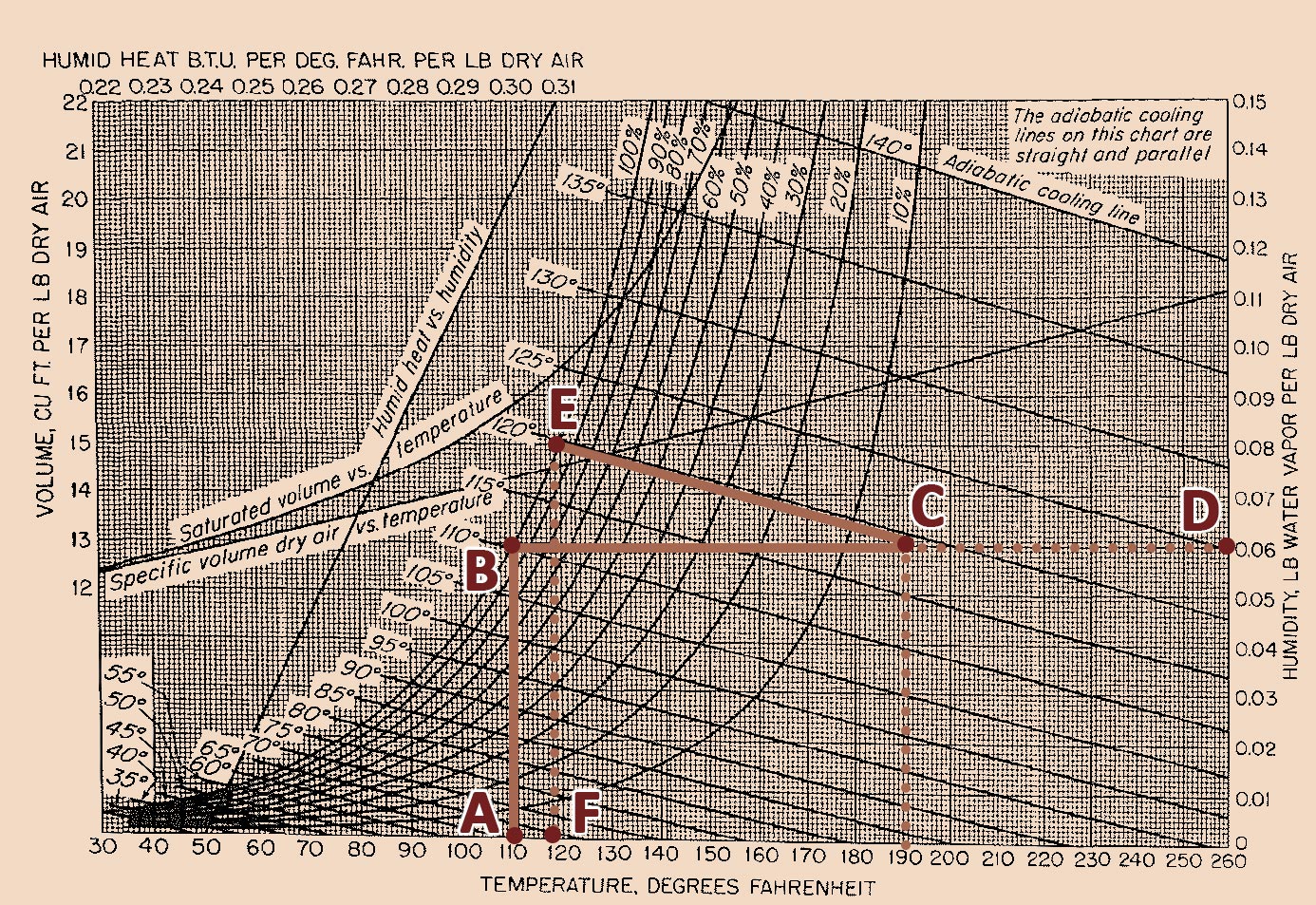
Humidity chart, also known as psychrometric chart, is a convenient diagram showing the properties of the gas-vapor mixture. Referring to this chart, engineers can easily determine the mixture’s properties in a specific pressure. A chart for air-water system at 1 atm is shown below. In this chart, various properties are plotted based on humidity and dry bulb temperature.
The curve lines marked with percentages indicate relative humidity. The curve line marked with 100 percent gives the humidity of saturated air as a function of temperature. The straight lines running downward and to the right of the saturation line are called adiabatic cooling lines. As mentioned before, they are the same as psychrometric lines for air-water system.
Figure 2. Humidity- Psychrometric chart of air-water system at 1 atm
How to use humidity chart
The usefulness of humidity chart is shown by the following example as illustrated on figure 2. Assume that an atmospheric stream of air has a temperature 190°F and a dew point 110°F. If we plot a vertical straight line from point A (110°F), it intersects the 100% saturation curve at point B which indicates the dew point. From point B we move to right side horizontally until point C which is the intersection of constant temperature line for 190°F. The humidity then can be read from point D. In order to find wet bulb and adiabatic saturation temperature, follow adiabatic cooling line through point C to its intersection, point E, on the 100% saturation line. Point F is the wet bulb temperature. Interpolation between adiabatic lines may be necessary.
Measurement of humidity
The humidity of a gas can be found by two regular methods in industrial applications. Dew point measurement or wet bulb temperature measurement.
- Dew point method: it can be done by inserting a plate into gas and gradually reduce the plate’s temperature until mist condenses on the surface. It is therefore the dew point. To check the reading, slowly increase plate’s temperature until the mist disappears. From the average of these two temperatures, the humidity can be read from a humidity chart.
- Psychrometric method: By determining the wet bulb and dry bulb temperatures simultaneously, one can find the humidity from humidity chart using psychrometric line. The observed wet bulb temperature is the place where the psychrometric line intersects saturation (100%) line.
Nomenclature (SI units)
H Humidity- kg vapor/kg vapor-free gas
Cp Specific heat- J/kg.°C
Cs Humid heat- J/kg.°C
HR Relative humidity- %
hy Heat transfer coefficient of gas side- W/m2.°C
ky Mass transfer coefficient- kgmol/m2.s
M Molecular weight- kg/kgmol
PA Partial pressure of vapor- Pascal
P*A Vapor pressure of liquid- Pascal
Tw Wet bulb temperature- °C
Ts Adiabatic saturation temperature- °C
\lambda Latent heat of vaporization- J/kg
Reference
Warren L. McCabe, Julian C. Smith, and Peter Harriot: Unit Operation of Chemical Engineering, 5th ed., McGraw-Hill, New York, 1993.


Leave A Comment