
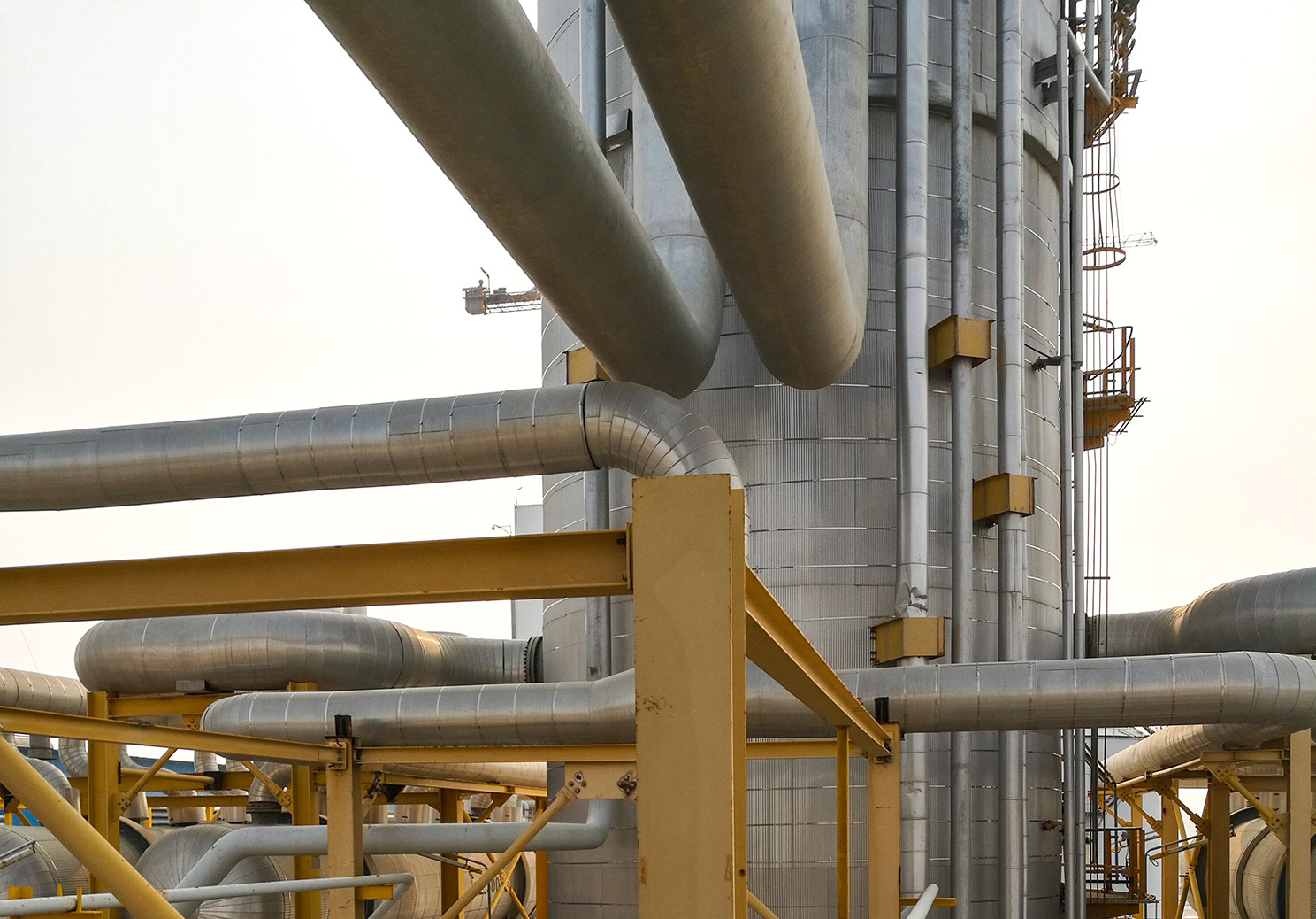
In every oil and gas project, there are tons of lines and networks of pipes. Each one of these pipes has a specific size. It is essential for process engineers to calculate the best size for each line. Thus, there is a need for a specific criterion to provide the general line sizing standards. In fact, for every oil and gas project, there exists a unique document called “Design Basis” or “Process Sizing Criteria”, which is intended to be used as a reference to calculate the proper size of each line and other equipment. In the following section, we will review the general principle of petrochemical line sizing criteria and its procedures, which is common among most refinery and petrochemical plants.
Line sizing procedures
There are a couple of steps in order to achieve the optimum pipe size. Optimum pipe size has the following characteristics:
- Economic (in terms of material, construction, installation)
- Allowable fluid velocity
- Low pressure drop
- Available material
Petrochemical line sizing criteria are based on two major parameters, maximum allowable pressure drop and velocity. Generally, the more the velocity, the more the pressure drop. Therefore, one cannot decrease the pipe size too much in order to achieve an economic design. Otherwise, pressure drop and velocity would exceed their maximum limits. Now, let’s take a look at pipe sizing procedures. We will explain each step accordingly.
- Choose a velocity based on the criteria and calculate the pipe internal diameter (ID).
- Calculate the pressure drop (dP) and check it with the criteria.
- Calculate pipe thickness and schedule based on the design pressure and pre-determined pipe diameter.
- Determine the new ID using defined schedule and calculate velocity & dP again based on new ID and check with the criteria.
- Analyze flow hydraulic & phenomena. (Flow mapping)
Step 1. Initial pipe ID determination
In this step, we have to select a value for velocity that is lower than maximum limit. Each project has a unique document in which, maximum velocity & pressure drop limits for various services are specified. Therefore, engineers have to refer to this document for proper velocity & pressure drop determination.
For two-phase flows, erosion velocity is the maximum allowable velocity that shall be satisfied. According to API (American Petroleum Institute) RP 14E , erosion velocity is the velocity at which the pipe internal surface may start to erode: { V }_{ e }=\frac { c }{ \sqrt { { \rho }_{ m } } } Where: { \rho }_{ m }=\frac { { \dot { m } }_{ l }+{ \dot { m } }_{ g } }{ \frac { { \dot { m } }_{ l } }{ { \rho }_{ l } } +\frac { { \dot { m } }_{ g } }{ { \rho }_{ g } } } { V }_{ e } = erosion velocity
c = empirical constant
{ \rho }_{ m } = gas/liquid mixture density
{ \dot { m } }_{ l } = liquid mass flowrate
{ \dot { m } }_{ g } = gas mass flowrate
{ \rho }_{ l } = liquid density
{ \rho }_{ g } = gas density
“c” is a function of corrosiveness of the fluid and whether the service is continuous or intermittent. One can take c=122 (SI unit) as a conservative value for continuous services. For two phase low pressure services, It is recommended to consider a margin of 65% of erosion velocity for maximum velocity limit.
As a rule of thumb, the following rough figures are mostly used as petrochemical line sizing criteria for velocity & pressure drop limits:
| LIQUID | Nominal Pipe Size | Max Velocity (m/s) | Max \Delta P (bar/100m) |
|---|---|---|---|
| Pump suction | Lower than 8″ | 1 | 0.1 |
| Pump suction | Higher than 8″ | 2 | 0.1 |
| Pump discharge | Lower than 8″ | 2 | 0.5 |
| Pump discharge | Higher than 8″ | 3.5 | 0.5 |
Table 1. General velocity & pressure drop limits for petrochemical and refinery plants – Liquid Flow
| GAS & VAPOR | Operating Pressure | Max Velocity (m/s) | Max \Delta P (bar/100m) |
|---|---|---|---|
| Gas | Lower than 7 barg | 30 | 0.1 |
| Gas | Higher than 7 barg | 30 | 0.4 |
| Steam | LPS | 12\sqrt { d } (note 1) | 0.1 |
| Steam | MPS | 9\sqrt { d } (note 1) | 0.5 |
Table 2. General velocity & pressure drop limits for petrochemical and refinery plants – Gaseous Flow
| TWO PHASE | Max Velocity (m/s) | Max \Delta P (bar/100m) |
|---|---|---|
| High pressure flow | Ve | 0.45 |
| Low pressure flow | 0.65 Ve | 0.45 |
Table 3. General velocity & pressure drop limits for petrochemical and refinery plants – Two Phase Flow
After identifying the velocity, calculate pipe internal diameter using volumetric flowrate. It’s recommended to consider 10% overdesign for the fluid flowrate.
Note 1: d= pipe’s diameter in inch
Step 2. Pressure drop calculation
Having determined pipe ID, calculate fluid pressure drop using the related dP equations and formulas. This is usually done by conventional engineering software. Check the calculated dP with the related criteria. If it exceeds the maximum limit, return to step one and repeat the calculations for a lower velocity.
Step 3. Thickness calculation
In this step, we have to calculate pipe thickness which is done by piping department. For every project, there is a document called piping & material specification (PMS). In this document, all the available piping materials, sizes and pressure rating classes are specified. Design engineers usually refer to PMS in order to specify pipe’s pressure class and thus the proper schedule (thickness). In PMS, schedule is a function of design pressure, temperature and line service. However, PMS itself is calculated based on mechanical stress-relating correlations. ASME B31 provides complete sets of correlations to calculate various pipes thicknesses.
The following equation can be used for straight process pipes, which are under internal pressure. Mostly utilized in petrochemical or refinery plants: (Only valid for t < Do /6) { t }_{ m }=t+c t=\frac { { P }_{ d }{ D }_{ o } }{ 2\left( SE+{ P }_{ d }Y \right) } Where:
- tm = Minimum final thickness. The minimum thickness for the pipe selected, considering manufacturer’s minus tolerance, shall not be less than tm . The minus tolerance for seamless steel pipe is 12.5% of the nominal pipe wall thickness.
- t = Calculated thickness (inch)
- c = Corrosion allowance. For carbon steel, based on the corrosiveness condition, the normal values are 1.6/ 3.2/ 6 (mm).
- Pd = Design pressure (psig). This parameter shall be determined by process engineers based on operating pressure and the predicted over-pressure scenarios.
- Do = Outside diameter (inch). It can be determined based on pipe ID using pipe table. Note that for pipes with nominal pipe size (NPS) more than 14”, NPS is equal to Do . Otherwise NPS < Do .
- S = Allowable stress (psi). It is a function of material grade and metal temperature. The more the metal temperature, the less the allowable stress. An approximate value for most steels at medium temperature is 20000 psi.
- E = Quality factor – or joint efficiency (dimensionless). It is a function of material grade and pipe’s fabrication method. For seamless pipe E=1. For most steel castings it can be approximated by 0.8.
- Y = Coefficient of temperature (dimensionless). For almost all metals except cast iron at temperature smaller than 480° C, Y=0.4. For cast iron Y=0.
After calculation of minimum thickness (tm), refer to pipe tables and choose an appropriate schedule for the selected NPS. The schedule shall be selected with a minimum thickness of tm .
Pipe tables provide specifications of standard pipes used in industry. Since there are only limited values available for thickness of different NPS, engineers use pipe tables to select a proper schedule among available dimensions. ASME B36.10 & B36.19 cover the standardization of dimensions of steel and stainless steel pipes.
Step 4. Checking the velocity and dP for the new ID
After choosing the proper pipe schedule for the selected NPS, specify pipe ID again based on the new thickness, using pipe table. Then, calculate the velocity and dP for the new ID and check them with the criteria. If they don’t meet the criteria, return to step three and use a bigger NPS.
Step 5. Analysis of flow hydraulic & phenomena
Flow mapping is done after specifying pipe’s dimensions. Engineers have to analyze flow hydraulic prior to pipeline fabrication by means of flow assurance software. This step is especially essential if there is a probability for the flow to enter two phase regimes. In this case, hydraulic analysis shall be done for both maximum flow (110% normal) and minimum flow (30% normal). This step includes the following activities:
- Erosion checking
- Wax deposition
- Hydrate formation (usually for pipelines)
- Slug analysis
- Corrosion rate estimation
- Static flow regime
- Dynamic flow evaluation (startup- shutdown)
Conclusion
In this article, we studied some basic principles of petrochemical line sizing criteria and pipe design. Technically, this procedure has to be done via trial and error. For each initial guess, all the possible consequences have to be considered. In order to achieve the best design, it requires a whole team of engineers from different departments to cooperate. In addition to report the final calculation for the desired pipe size, process engineers usually include calculations for one size bigger and one size smaller for all the lines.
Economic considerations are extremely important. Optimum design is an economic one. Therefore, they have to be studied thoroughly from the raw materials weight to welding cost, corrosion inhibition, installation requirements (underground/rack) and insulation cost.
Consequently, these line sizing criteria are unique for each project. Therefore, the calculation shall be done according to their specific design basis.
Note: This information is for general knowledge only and shall be used under specialist’s supervision.
Leave A Comment